M2, M3, M4 Installation Instructions
Cutting the Profiles to Length
The profile length depends on the type of corner piece used:
A and D corner piece types: inner duct length minus 4 mm
S and B corner piece types: inner duct length minus 30 mm
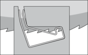
Most circular saws are suitable to cut the profiles. Make sure to clamp the profile on both sides of the saw blade over as much surface as possible in order to restrict any movements. This will protect the sawing blade and your ears! If possible, clamp the profile section in the position as illustrated and note the direction of rotation of the sawing blade. This will ensure that the burrs remain in the inaccessible spots of the flange.
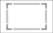
Frame Assembly
Assemble the frames vertically, and not horizontally.
a) Insert two corner pieces in the ends of both longer profile sections.
b) Insert the two shorter profile sections on one of the profile corners.
c) Insert the second longer profile with its corners into the shorter profiles.
The corner pieces are designed to fit closely into the profile inner shape. A rubber mallet might therefore be necessary to insert them into the profile ends.
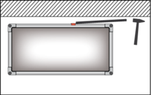
Frame Seating
Start at one of the upper corners and hammer along the line of the duct (not at the outer edge of the profile). To enable the profile to fit more easily hold it in a slightly inclined position. We recommend to fit the flanges with the duct in a horizontal position. Fit the flanges to both duct ends before fixing. Work on a table or any other flat surface allowing the duct to align itself. To avoid distortion, particularly on small ducts, check if the flanges are aligned on both ends before fixing. On ducts less than 1500 mm long, the flanges can be fitted in the vertical position.
Fixing the Frame
It is essential that the flange is securely fixed at the corners (i.e. spot-welding, stitching or blind rivets), where the maximum strength is required. There should be two fixing points with a maximum distance of 20 to 30 mm from each other and as close as possible to the ends of the profile sections. It is also very important that the flange is fully seated against the edge of the duct before fixing. Suitable fixing methods are spot welding, pressure jointing or blind riveting. As soon as the corners have been securely fixed, each length of profile is fixed at a spacing between 80 mm (M2 and M3 profiles) and 120 mm (M4 profiles). For profiles exceeding 600 mm a center fixing is required. Make sure that the flange is fully seated and check the duct alignment before fastening.
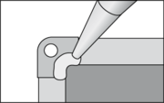
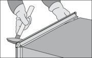
Sealing of the Corners
The sealing of the corners is important as they can often be a source of leakage. Due to irregularities in the length of the duct walls (i.e. offset seams), a gap can easily be formed which cannot be bridged by the duct´s sealing gasket. Injecting mastic sealant into the pockets of the corner can prevent this leakage risk. The corner pocket should be filled flush with sealant to the face of the flange and over the edge of the duct.
CLAMP RECOMMENDATIONS
The following applies only to products made of galvanized steel using A or S corner pieces
G-Clamp Installation Instructions
Hook the G-Clamp over the profile bead and tighten the bolt. Avoid over-tightening as this could deform the profile and/or the clamp:

Drive Clamps Installation Instructions
The flanges must be forced together either by tightening the corners or by using pliers, grips or other suitable tools before fitting the Drive Clamp. On flanges using S or B type corner pieces, the clamp can be fitted after bolting the corners together. On flanges using A type corners, the drive clamp must be fitted before the corners are bolted together:

Installation Tip:
Thanks to its thick end-face, the drive clamp can be driven into position in confined spaces with a piece of pipe for instance.
Clamps are required for the following duct widths:
Up to 1000 Pa
M2-0,7-Profile and M2-0,9-Profile: starting at KL 1200 mm
M3-0,8-Profile: starting at KL 1300 mm
M3-0,9-Profile and M3-1,2-Profile: starting at KL 1500 mm
M4-1,2-Profiel and M4-1,5-Profile: starting at KL 2000 mm
Above 1000 Pa
M2-0,7-Profile and M2-0,9-Profile: starting at KL 1000 mm
M3-0,8-Profile: starting at KL 1100 mm
M3-0,9-Profile and M3-1,2-Profile: starting at KL 1200 mm
M4-1,2-Profile and M4-1,5-Profile: starting at KL 1500 mm
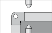
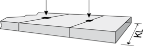
Explanations:
In this case an optimal flange support is reached, since the
duct walls (A) run vertically on both sides into the profile.
Fewer clamps are required for that reason.

Clamps are required for the following duct widths:
Up to 1000 Pa
M2-0,7-Profile and M2-0,9-Profile: starting at KL 1000 mm
M3-0,8-Profile: starting at KL 1100 mm
M3-0,9-Profile and M3-1,2-Profile: starting at KL 1200 mm
M4-1,2-Profiel and M4-1,5-Profile: starting at KL 1500 mm
Above 1000 Pa
M2-0,7-Profile and M2-0,9-Profile: starting at KL 800 mm
M3-0,8-Profile: starting at KL 900 mm
M3-0,9-Profile and M3-1,2-Profile: starting at KL 1000 mm
M4-1,2-Profile and M4-1,5-Profile: starting at KL 1200 mm
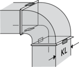
Explanations:
Angled or bent duct walls do not provide an optimal support to the flange. In these cases (please refer to the examples below) more clamps are required.


Important:
The above recommendations are not applicable to flexible joints, since support from the duct wall is lacking. The duct work manufacturer should therefore determine the number of clamps required according to the kind of flexible joint used. The above recommendations are based on tests which have been conducted on test duct work according to the norms DIN EN 1507. Other duct constructions, insufficiently stiffened duct walls, different sheet metal thickness, bad quality locks and so on may have negative effects on the duct work stability. The execution of the duct construction according to the above recommendations constitutes therefore no guarantee for sufficient duct stability and does not take away the responsibility from the duct work manufacturer to conduct his own tests. Special conditions such as pulsating air, sudden pressure changes, vibrations, man loads, damaged duct, etc. have not been taken into consideration. In such cases the duct work should be manufactured and tested according to these requirements.