Profile
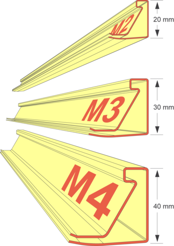
PROFILE M2, M3, M4
Noch heute gelten unsere Profile und Eckwinkel als die Stabilsten auf dem Markt.
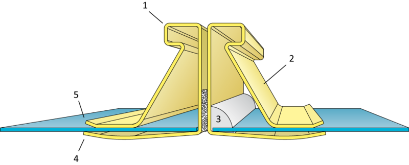
- Wulst an der Außenkante des Profils für das Anbringen von Zwischenverbindern.
- Der schräge Stützschenkel ist ausschlaggebend für die optimale Stabilität. Gemeinsam mit den Eckwinkeln sorgt er für eine geringe Durchbiegung.
- Profile sind optional auch mit eingespritzter Dichtmasse (hd-Ausführung) lieferbar.
- Der gewölbte Innenschenkel legt sich als metallische, anpassungsfähige Lippendichtung an die Kanalwand an und garantiert damit die hohe Luftdichtheit der METU-Profile.
- Diese Anfädelschräge (optional) erleichtert das Einführen der Kanalwand in das Flanschprofil.
Stabilität von METU-Profilen
Verformungsmessungen an Luftkanälen und Teilen von Luftkanalverbindungen: Seit ihrer Markteinführung (Patent Nr. 1 946 547 vom 13.09.1969) ermöglichen METU-SYSTEM Flanschprofile durch ihre Dreiecksform (MM, HM, RM), Kanalverbindungen mit optimaler Stabilität. Eine unabhängige MPA-Prüfung bestätigt im Oktober 1972 die überragende Stabilität der METU-SYSTEM Flanschprofile im Vergleich zu anderen Flanschprofilen, bzw. zu damals üblichen Verbindungsmethoden für Luftkanäle (z.B. Winkeleisen).
Die METU-Kanalverbindungen werden von vielen Anwendern als die Stabilsten auf dem Markt angesehen, wodurch die Verwendung von Zwischenverbindern (Klammern) reduziert oder sogar eliminiert wird. Keine EX / ATEX Zertifizierungen.
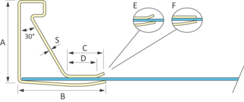
Profilabmessungen
hd = mit eingespritzter Dichtmasse (siehe ZI-401)
E = mit Anfädelschräge (mit A).
F = ohne Anfädelschräge (ohne A).
Informationen zu Materialien sehe ZI-101
Maximale Kanalwandstärke:
M2-0,7-Profil = 1,0 mm
M2-0,9-Profil = 1,0 mm
M3-0,8-Profil = 1,0 mm
M3-0,9-Profil = 1,0 mm
M3-1,2-Profil = 1,2 mm
M4-1,2-Profil = 1,2 mm
M4-1,5-Profil = 1,2 mm
| Art.Nr. | Bezeichnung | A | B | C | D | S | L |
| A01A-2001 | M2-0,7-Profil verz (ohne A) | 20 | 25 | 13 | - | 0,7 | 5000 |
| A01A-2002 | M2-0,7-Profil verz hd (ohne A) | 20 | 25 | 13 | - | 0,7 | 5000 |
| A01A-2003 | M2-0,7-Profil verz (mit A) | 20 | 25 | 13 | 10 | 0,7 | 5000 |
| A01A-2004 | M2-0,7-Profil verz hd (mit A) | 20 | 25 | 13 | 10 | 0,7 | 5000 |
| A01A-2009 | M2-0,9-Profil verz (ohne A) | 20 | 25 | 11 | - | 0,9 | 5000 |
| A01A-2010 | M2-0,9-Profil verz hd (ohne A) | 20 | 25 | 11 | - | 0,9 | 5000 |
| A01A-2011 | M2-0,9-Profil verz (mit A) | 20 | 25 | 11 | 8 | 0,9 | 5000 |
| A01A-2012 | M2-0,9-Profil verz hd (mit A) | 20 | 25 | 11 | 8 | 0,9 | 5000 |
| A01B-2015 | M2-0,8-Profil V2A ohne Folie (ohne A) | 20 | 25 | 11 | - | 0,8 | 5000 |
| A01C-2009 | M2-0,8-Profil Alu (ohne A) | 20 | 25 | 11 | - | 0,8 | 5000 |
| A01A-3005 | M3-0,8-Profil verz (ohne A) | 30 | 32 | 15 | - | 0,8 | 5000 |
| A01A-3006 | M3-0,8-Profil verz hd (ohne A) | 30 | 32 | 15 | - | 0,8 | 5000 |
| A01A-3007 | M3-0,8-Profil verz (mit A) | 30 | 32 | 15 | 11 | 0,8 | 5000 |
| A01A-3008 | M3-0,8-Profil verz hd (mit A) | 30 | 32 | 15 | 11 | 0,8 | 5000 |
| A01A-3009 | M3-0,9-Profil verz (ohne A) | 30 | 32 | 15 | - | 0,9 | 5000 |
| A01A-3010 | M3-0,9-Profil verz hd (ohne A) | 30 | 32 | 15 | - | 0,9 | 5000 |
| A01A-3011 | M3-0,9-Profil verz (mit A) | 30 | 32 | 15 | 8 | 0,9 | 5000 |
| A01A-3012 | M3-0,9-Profil verz hd (mit A) | 30 | 32 | 15 | 8 | 0,9 | 5000 |
| A01A-3013 | M3-1,2-Profil verz (ohne A) | 30 | 32 | 15 | - | 1,2 | 5000 |
| A01A-3014 | M3-1,2-Profil verz hd (ohne A) | 30 | 32 | 15 | - | 1,2 | 5000 |
| A01A-3015 | M3-1,2-Profil verz (mit A) | 30 | 32 | 15 | 8 | 1,2 | 5000 |
| A01A-3016 | M3-1,2-Profil verz hd (mit A) | 30 | 32 | 15 | 8 | 1,2 | 5000 |
| A01B-3015 | M3-0,8-Profil V2A ohne Folie (ohne A) | 30 | 32 | 15 | - | 0,8 | 5000 |
| A01C-3009 | M3-0,8-Profil Alu (ohne A) | 30 | 32 | 15 | - | 0,8 | 5000 |
| A01C-3013 | M3-1,2-Profil Alu (ohne A) | 30 | 32 | 15 | - | 1,2 | 5000 |
| A01A-4013 | M4-1,2-Profil verz (ohne A) | 40 | 40 | 17 | - | 1,2 | 5000 |
| A01A-4014 | M4-1,2-Profil verz hd (ohne A) | 40 | 40 | 17 | - | 1,2 | 5000 |
| A01A-4017 | M4-1,5-Profil verz (ohne A) | 40 | 40 | 17 | - | 1,5 | 5000 |
| A01A-4018 | M4-1,5-Profil verz hd (ohne A) | 40 | 40 | 17 | - | 1,5 | 5000 |
| A01B-4015 | M4-1,2-Profil V2A ohne Folie (ohne A) | 40 | 40 | 17 | - | 1,2 | 5000 |
| A01B-4016 | M4-1,2-Profil V2A hd ohne Folie (ohne A) | 40 | 40 | 17 | - | 1,2 | 5000 |
| A01C-4017 | M4-1,5-Profil Alu (ohne A) | 40 | 40 | 17 | - | 1,5 | 5000 |
Trägheits- und Widerstandsmomente von METU-SYSTEM Profilen aus verzinktem Stahl
Die folgenden Zahlen sind nur Indikationen und können nicht das eigene Urteil der Anwender in Bezug auf Konstruktionen ersetzen. Die Stabilität ist abhängig von der Kanalblechstärke.
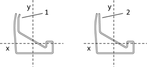
1. Mit A (mit Anfädelschräge)
2. Ohne A (ohne Anfädelschräge)
cm4: Trägheitsmomente x / y im Schwerpunkt
cm3: Widerstandsmomente x / y im Schwerpunkt
| cm4 ( Ixs / Iys ) | cm3 ( Wxs / Wys ) | ||
| A01A-2001 | M2-0,7-Profil (ohne A) | 0,3284 / 0,3037 | 0,2012 / 0,2242 |
| A01A-2003 | M2-0,7-Profil (mit A) | 0,3265 / 0,3018 | 0,2000 / 0,2234 |
| A01A-2009 | M2-0,9-Profil (ohne A) | 0,3183 / 0,3871 | 0,2135 / 0,2853 |
| A01A-2011 | M2-0,9-Profil (mit A) | 0,3164 / 0,3843 | 0,2168 / 0,2842 |
| A01A-3005 | M3-0,8-Profil (ohne A) | 0,7200 / 1,0250 | 0,3560 / 0,5480 |
| A01A-3007 | M3-0,8-Profil (mit A) | 0,7150 / 1,0180 | 0,3590 / 0,5450 |
| A01A-3009 | M3-0,9-Profil (ohne A) | 0,8150 / 1,1520 | 0,4000 / 0,6120 |
| A01A-3011 | M3-0,9-Profil (mit A) | 0,8090 / 1,1440 | 0,4080 / 0,6090 |
| A01A-3013 | M3-1,2-Profil (ohne A) | 1,2250 / 1,6010 | 0,5880 / 0,8150 |
| A01A-3015 | M3-1,2-Profil (mit A) | 1,2180 / 1,5900 | 0,5970 / 0,8120 |
| A01A-4013 | M4-1,2-Profil (ohne A) | 2,4160 / 3,6760 | 0,9150 / 1,4330 |
| A01A-4017 | M4-1,5-Profil (ohne A) | 3,0820 / 4,5630 | 1,1660 / 1,7460 |
Alle bereitgestellten Informationen sind Richtwerte.