MS Instructions
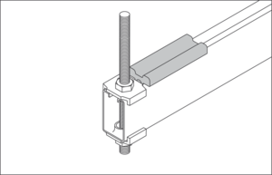
The MS End Bracket is inserted as a connecting part between the Hanger Profile and the threaded rod. Advantages: a high load capacity, an aesthetically pleasing appearance, does not dependent on the profile hole locations.
When only one duct is going to be suspended, the Hanger Profile section is cut 20 to 40 mm longer than the duct width. For all other applications, cut the Hanger Profile sections according to your needs.
If isolation is required, first insert the Isolation Pads on both ends of the Hanger Profile.
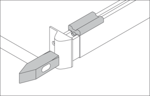
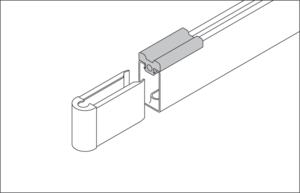
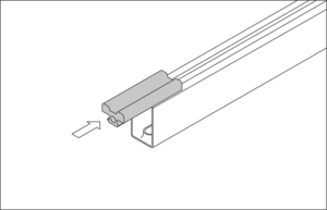
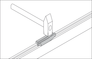
The End Brackets are slightly tapered so that they wedge into the profile and must be hammered home hard up to the stop. To prevent the End Bracket from being damaged, the protective cap (A) which is included in each sack of End Brackets, should be used.
The End Bracket can be fitted into short profiles in a vertical position. Long Profiles should be put in a horizontal position, against a wall for instance, in order to hammer in the End Brackets.
Max. threaded rod Ø for:
- End Bracket MS 3 = M8
- End Bracket MS 5 = M10
- End Bracket MS 8 = M12
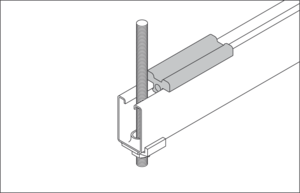
If the maximum threaded rod diameters are used, no washers are needed.
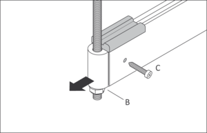
If smaller threaded rod diameters are used, corresponding washers (B) must be installed.
If in some special cases the End Bracket is not sufficiently secured, it is possible to secure it in place with screws or rivets (C).
Loading capacity (*):
- MS 3 ≈ max. 1000 N
- MS 5 ≈ max. 3000 N
- MS 8 ≈ max. 5000 N
Without additional fastening the End Bracket is pulled out at:
- MS 3 ≈ 150 N
- MS 5 ≈ 400 N
- MS 8 ≈ 150 N
As an alternative to the End Bracket, the threaded rod can be passed through the oval holes of the Hanger Profile and fixed by a MS Clamp.
Max. threaded rod Ø for:
- Clamp MS 3 = M8
- Clamp MS 5 = M10
- Clamp MS 8 = M12
If the maximum threaded rod diameters are used, no washers are needed. If smaller threaded rod diameters are used, corresponding washers must be installed between the MS Clamp and the nut.
Loading capacity (*) :
- MS 3 ≈ max. 1000 N
- MS 5 ≈ max. 1500 N
- MS 8 ≈ max. 2500 N
A more stable connection between Hanger Profile and threaded rod is achieved by using two MS Clamps and nuts.
Loading capacity (*):
- MS 3 ≈ max. 1500 N
- MS 5 ≈ max. 2500 N
- MS 8 ≈ max. 3000 N
(*)
The indicated maximum load-bearing capacity is in accordance with the European Norm EN 12236 and can therefore be used integrally. The breaking load is three times higher.
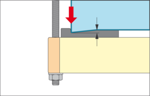
The use of MS Isolation Pads providaes a cost effective solution if sound isolation is required. Because the duct weight is mainly concentrated on the duct corners, the Isolation Pads installed at the corners have to support the most important loads. A rubber with 60° shore hardness has been chosen because of its high loading capacity. The effectiveness of the Isolation Pad decreases rapidly when it is overloaded.
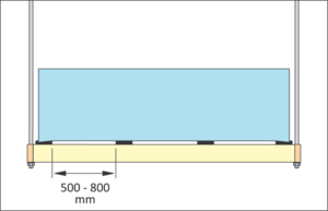
Normally only two Isolation Pads are required (one at each corner of the ductwork). On wide duct work, however, additional Isolation Pads must be installed to prevent the bottom of the duct from touching the Hanger Profile.
Isolation Pads Lengths:
MS 3 ≈ 60 mm
MS 5 ≈ 80 mm
MS 8 ≈ 100 mm
The bottom corners of the duct work greatly compress the Isolation Pads. Softer Isolators (foam rubber for example) may be compressed to such an extent that they become ineffective.
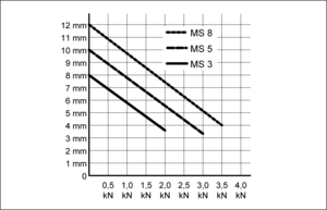
This graph gives an indication to which extent the Isolation Pad is compressed depending on different loading capacities.
Maximum loading capacities (*):
MS 3 ≈ 2000 N
MS 5 ≈ 3000 N
MS 8 ≈ 3500 N
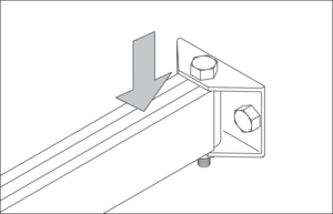
For a safe fixation of Hanger Profiles to a wall, Wall Brackets are fastened to the wall using screws or plugs:
MS 3 2 x M8
MS 5 2 x M10
MS 8 2 x M12
The Hanger Profile is connected to the Wall Bracket using a hex-bolt going through the Wall Bracket and the End Bracket installed at the end of the Profile.
Max. loading capacity (*) of the connection Wall Bracket and Hanger Profile:
MS 3 ≈ 1500 N
MS 5 ≈ 3000 N
MS 8 ≈ 4000 N
Hexagonal nut with bolt:
MS 3: M8 x 50
MS 5: M10 x 70
MS 8: M12 x 100
Caution:
The Wall Bracket is not suitable for cantilever brackets (projecting supports). The Hanger Profile must be supported at both ends.
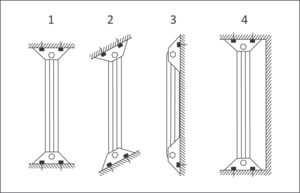
The position of the Hanger Profile respective to the wall can vary from parallel up to a right angle, thus providing a 180° range of possibilities. Please note that a position where the Hanger Profile is completely parallel to the wall is only possible when the Wall Bracket is fixed with only one screw to the wall. This consequently halves the maximum loading capacity.
1) On a right angle to the wall
2) Diagonally to the wall
3) Parallel to the wall
4) In a recess